How to Program Digital Inputs and Relay Contacts in the greenBOX
- Jun 30, 2025
- 17 min read
Trigger Actions. Send Signals. Automate Logic.
Ecogate’s greenBOX control units include programmable digital inputs and relay outputs that allow the system to interface with external devices, trigger advanced functions, and support site-specific automation.
This guide walks through how to use the greenBOX interface to configure these inputs and outputs—no PLCs or custom wiring logic required. Whether you’re activating Cleaning Mode, triggering a system reset from a button next to the fan, or signaling a warning or alarm, the setup is handled entirely through greenBOX’s built-in Adelie Programming Language (APL).
Both greenBOX Nxt and greenBOX Max include interface boards for connecting external signals and devices.
Each interface board provides four digital inputs and four relay outputs (dry contacts).
The greenBOX Nxt comes with one board (4 inputs, 4 relays).
The greenBOX Max includes two boards, for a total of 8 inputs and 8 relays.
Larger models can support even more by adding additional interface boards.
Digital inputs can receive signals from buttons, switches, sensors, or other devices to trigger actions like:
Duct cleaning mode
Full-system bypass
Emergency shutdown (e.g., spark detector trigger)
Winter Mode to protect filters in freezing conditions
System error resets
Relay contacts can be configured to output signals based on the same types of conditions—whether it’s turning on a transport fan when any system is active, sending a start/stop pulse to a dust collector, or signaling a building management system when airflow drops below target.
Throughout this guide, we’ll walk through real examples that show how to configure digital inputs and relays using the greenBOX interface. You’ll also find reference material outlining every available trigger type and status condition, so you can build the logic your system needs.
Connecting greenBOX Digital Inputs
To connect a switch or dry-contact relay to a digital input, simply wire it between the input terminal and GND. The greenBOX interface board supplies its own 24V DC signal, current-limited to 10mA, so never apply external voltage to the input. Inputs are optically isolated from the processor for safety and noise immunity—similar to standard PLC or VFD inputs.
All digital inputs share a common GND terminal. If your application requires more than four inputs, use a greenBOX Max or Master, which support additional interface boards.
Monitoring Digital Inputs
Each digital input has a yellow LED above the terminal that lights when the input is active. You can also monitor input status on the OLED screen of the interface board by pressing the touch button three times (page 4), or in the greenBOX user interface under: Monitoring → Interface Board
Connecting greenBOX Relay Contacts
Each interface board includes four dry-contact relays:
Three relays provide Normally Open (NO) contacts
One relay provides both Normally Open (NO) and Normally Closed (NC) contacts
Relays are rated for 1A at 24V DC. They can be used to control devices like dust collectors (when a Power Master VFD is not used), or to signal errors and warnings to external systems like building automation. For more than four relay outputs, use a greenBOX Max or Master with multiple interface boards.
Monitoring Relay Contacts
Relay status is indicated by a red LED above the terminal when the contact is active (closed). You can also monitor relay status on the OLED screen (press the touch button three times to reach page 4), or in the greenBOX UI under: Monitoring → Interface Board

Programming Logic: Inputs, Outputs, and Triggers
The greenBOX interface gives you full control over how your system responds to external signals and internal conditions. Both digital inputs and relay outputs can be programmed using the same intuitive interface — no PLC required.
Through the built-in listbox-style programming environment (Adelie), you can configure exactly what should happen when a signal is received, a condition is met, or a status changes.
Trigger Types: What Can Drive an Action
Triggers can be based on any of the following:
Digital Inputs
External signals—such as push buttons, timer switches, or dry contacts—can be wired to the greenBOX interface board and used to trigger actions like:
Cleaning Mode
Bypass
Security Shutdown
Winter Mode
System Error Reset
Analog Values
The system can also respond to live analog inputs such as:
Outside temperature
In-duct temperature
Fan or filter pressure
Air velocity
Air volume or surplus
These values are automatically available in metric or imperial units depending on your greenBOX localization settings.
System Status
You can also use internal system states—like fan status, gate conditions, system errors, or custom mode activations—as triggers. This allows you to build logic based on the current behavior of the system itself.
A complete list of trigger sources and options is available in Appendix A.
Combining Multiple Conditions
You’re not limited to a single trigger. Use logical operators to combine multiple conditions for precise control:
OR: Trigger if any condition is true
AND: Trigger only if all conditions are true
XOR, NOR, NAND: Additional logical combinations for advanced setups
This allows you to create multi-variable logic—such as starting a fan only if a temperature is low and a door switch is closed.
Using Timers
The Edge Timer allows you to generate a timed relay pulse based on a signal change:
Rising Edge: Triggers when a signal becomes active
Falling Edge: Triggers when a signal becomes inactive
Rising + Falling Edge: Triggers on both transitions
Continuous: Holds the relay active as long as the trigger condition is met (no pulse)
This is useful for actions like sending a 2-second start pulse to a dust collector, or generating a momentary signal to a building automation system.
Custom Naming
Every system, sensor, and input in your greenBOX setup can be named. These names carry through into the programming interface, making logic easier to build and understand. Instead of “System 3 Status,” you can work with labels like “Main CNC Line” or “North Duct Zone.”
Future Expansion
Ecogate has designed the programming environment to grow with user needs. While current options focus on the most-requested triggers and actions, future updates will allow users to program any connected device—including Smart Gates, VFDs, Modbus sensors, and internal system values.
New programming capabilities will roll out progressively throughout 2025 via free software updates.
Digital Inputs Programming Examples
The following examples show how to configure greenBOX digital inputs for common use cases. Each input can trigger specific system functions like Cleaning Mode, Bypass, Winter Mode, and more — all programmable through the greenBOX interface.
Example 1: Trigger Cleaning Mode with a Button
The Cleaning Mode opens all gates and runs the fan at a user-defined cleaning speed. While this can be scheduled or automatic, it’s often helpful to start cleaning manually — for example, after a messy operation or before shutdown.
In this example, we assign Cleaning Mode to Digital Input 1 on the Left Interface Board of a greenBOX Max.
To begin, open the user interface and go to:System Settings → 08. External Signals

Click the ⊕ (or pencil icon) to edit the Cleaning function. Click + ADD TRIGGER, then select:
Interface Board Left Digital Inputs
Digital Input 1
Leave the default condition as "is active"
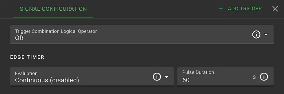


Next, click SIGNAL CONFIGURATION. Under Evaluation, choose Rising Edge Pulse and set Pulse Duration to 600 seconds (10 minutes). This means the input will activate Cleaning Mode for 10 minutes when pressed.
Once confirmed as Valid, the function is live and can be used while the system is running — no restart needed.


Example 2: Trigger Bypass Mode for Cleaning After Shift
Some facilities use Bypass Mode after shifts to run manual cleanup operations while machines are off. In Bypass Mode, all gates open and the fan runs at a fixed speed — allowing general air cleanup without machine activity.
In this setup, we assign Bypass Mode to Digital Input 2 on the Left Interface Board. You can use a toggle switch, spring-wound timer, or other dry contact to trigger the input.

Note: Bypass Mode ignores any gates set to “Open Only by Sensor.” Fan speed during bypass is adjustable in Fan → Advanced Settings.
Example 3: Use Digital Input as Security Input (e.g. Spark Detection)
The Security Input is used for safety devices such as spark detectors, fire alarms, or emergency shutdown triggers. When active, it immediately stops the system.
To maximize reliability, security inputs should use Normally Closed dry contacts. This ensures the system shuts down if the wire is damaged or disconnected.
In this example, we assign the function to Digital Input 3 and set the trigger condition to "is not active" (since it's Normally Closed).

If the input is triggered while the system is running, it will stop and display an error. If triggered while idle, the system will reset automatically.
For larger systems, spark detectors are often wired directly to the Power Master VFD. The greenBOX Security Input is ideal for smaller systems where the fan is controlled via relay contact.
Example 4: Trigger Winter Mode Based on Temperature
At freezing temperatures, dust collectors can be damaged by ice forming on filter bags or cartridges. Traditional systems combat this by running the fan at full speed — wasting energy.
With Ecogate, Winter Mode runs the fan at a low idle speed to maintain airflow through the filters while minimizing power usage. This saves up to 90% of energy during idle antifreeze operation compared to full speed fan operation.
You can trigger Winter Mode using analog temperature sensors — either:
Ambient Air Temperature
In-Duct Air Temperature
We recommend using both sensors with a logical OR condition to increase reliability.
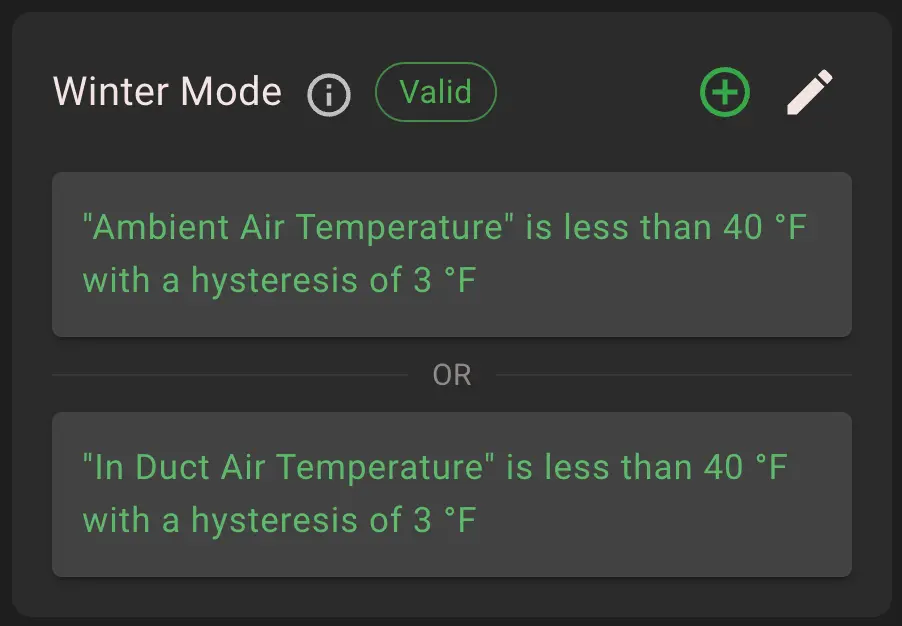
Set both temperature conditions to activate if below 40°F. Add hysteresis of 3°F to prevent the function from toggling on/off too rapidly. The fan will shut off Winter Mode only once the temperature rises above 43°F.
Fan speed for Winter Mode is adjustable in Fan → Advanced Settings.
For systems without temperature sensors, Winter Mode can also be triggered manually via digital input — but we recommend automatic sensor-based control for reliability.
Example 5: Reset System Error with a Button
In some shops, filter cleaning is performed manually during breaks with power disconnected from the fan. If the greenBOX loses communication with the VFD during this time, it logs an error that must be cleared.
While errors can be reset from the greenBOX touchscreen, it's often more convenient to install a remote reset button near the VFD or maintenance area.
In this example, we assign Digital Input 4 to trigger Error Reset.


These examples demonstrate how digital inputs can be used to extend control, safety, and convenience. The same intuitive logic can be applied to a wide range of devices — from sensors to switches — using simple programming steps.
Relay Contacts Programming
Relay outputs in the greenBOX system are programmed using the same logic structure as digital inputs. Each relay can be triggered by system status, external conditions, or analog values — allowing seamless integration with external devices such as fans, alarms, dust collectors, or building automation systems.
Each interface board includes:
Relays 1–3: Normally Open (NO) dry contacts
Relay 4: Configurable as Normally Open (NO) or Normally Closed (NC)
All relays are rated at 1A @ 24V DC.
To access relay programming: Service Mode → Interface Boards → Relays (If you need access to Service Mode, contact: support@ecogate.com)
Example 6: Start a Transport Fan When Any System is Running
In this setup, we want to start an auxiliary transport fan whenever any one of three systems is running. We assign this function to Relay 4.

Each system name shown is user-defined. The logic is as follows:
Trigger Relay 4 if Desktop Factory is Running
OR if F510 & EG Motor is Running
OR if VACON & REAL GATE is Running

Status values can be selected using conditions like "is" or "is not" — for example:“System is Running” or “System is not Running”


Example 7: Send a Start Pulse to a Dust Collector
Some dust collectors are controlled by external start/stop buttons. In this case, we use Relay 3 to send a 2-second pulse to simulate a button press.

In SIGNAL CONFIGURATION, choose:
Evaluation: Rising Edge Pulse
Pulse Duration: 2 seconds

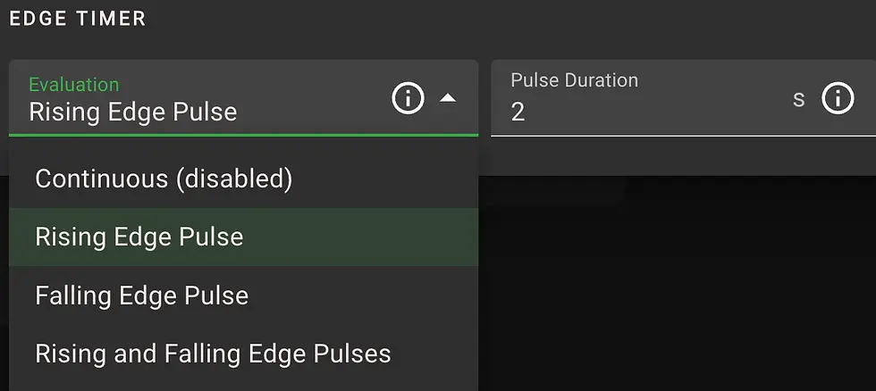
This setup sends a brief signal to the dust collector to initiate startup, aligned with greenBOX system status.
Example 8: Send a Stop Pulse to a Dust Collector
To stop the same collector, we use Relay 4’s Normally Closed (NC) contact. When triggered, this contact opens briefly — simulating a stop button being pressed.

Use the Off Delay system status as the trigger — this status is the last stage before shutdown, giving the collector time to clear residual dust.
Wire the NC contact in series with the collector’s Stop circuit. When triggered, the relay opens for 2 seconds and stops the unit.
Example 9: Signal if Any greenBOX Error or System Error Occurs
Use Relay 2 to trigger when any system enters an error state. This setup mirrors the Status Light’s red indicator and can be connected to an external alarm or notification system.
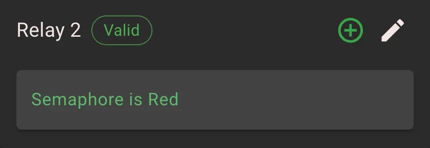

This can also be configured per system, but the global error signal is often most useful for centralized monitoring.
Example 10: Trigger if Air Volume Drops 15% Below Design
In some jurisdictions, building codes require an alarm if air volume falls below design thresholds. Ecogate makes this easy by continuously calculating Air Volume Surplus.
In this example, Relay 1 is used to close a contact if the measured airflow drops 15% below the design value.

How it works:
Design Air Volume is set during commissioning
greenBOX measures real-time airflow across all active gates
It calculates the difference — this is the Air Volume Surplus
If the surplus drops below -15%, the relay closes.
This allows the system to trigger warnings or shutdowns if airflow falls short of requirements.
Example 11: Trigger if Maximum Air Volume is Reached
Some systems must notify operators if the total system air volume exceeds the fan’s rated capacity — often required by AHJ or internal safety protocols.
In this example, Relay 2 is configured to close if airflow rises above the set maximum.

When this trigger is active, the system:
Stops opening new gates
Can issue a visual or audible warning
Closes the relay contact for external signaling or alarm integration
This protects the fan and duct system from overloading, and helps enforce operational limits.
Summary
The greenBOX control unit gives users a simple way to define how their system responds to inputs and conditions. No PLCs or external control logic are needed. Digital inputs and relay contacts can be programmed directly in the interface to trigger actions, control equipment, or send signals based on system behavior.
You can start a cleaning cycle with a button, send a pulse to a dust collector, or notify a building automation system when airflow drops. The same programming method applies across all use cases, making it easy to build reliable, repeatable logic.
This flexibility expands how the On-Demand Control System fits into your operation. Because all logic is handled within the greenBOX, there’s no need to involve additional control layers or third-party programming.
If a feature you need isn’t available yet, let us know. Many enhancements are driven by user requests. One of the most requested is the ability to send SMS alerts when certain conditions are met, such as filter pressure warnings or system faults. That and other improvements such as expanding this integration to our Precision Gates are scheduled for future software updates.
We're continuing to build out these tools based on real-world use. Your feedback helps shape what comes next.
Appendix A: All Digital Inputs And Relay Contacts Programming Options (Sources, Triggers)
Trigger Source: Semaphore Status (Status Light)
Note: Trigger Source "names" are user-defined
Trigger Values | Explanation | Recommended Use |
Any Error | This trigger is active if there is error in any system plus additional errors by interface board temperature, voltages, currents. | Create error for external control system or building automation PLC |
Green Light | This trigger is active if Green status light is active, which means all systems are OK. | Create error for external control system or building automation PLC |
Orange Light | This trigger is active if Orange status light is active, which means warning in any system. | Create error for external control system or building automation PLC |
Red | This trigger is active if Red status light is active, which means error in any system. | Create error for external control system or building automation PLC |
Trigger Source: "System Name" Air Measurements
Note: Trigger Source "names" are user-defined
Trigger Values | Explanation | Recommended Use |
Required Air Velocity | This trigger is active if Required Air Velocity is higher (lower) than set value in m/s or FPM. | |
Required Air Volume | This trigger is active if Required Air Volume is higher (lower) than set value in m3/h or CFM. | |
Measured Air Velocity | This trigger is active if Measured Air Velocity is higher (lower) than set value in m/s or FPM. | To create alarm if air velocity is too low |
Measured Air Volume | This trigger is active if Measured Air Volume is higher (lower) than set value in m3/h or CFM. | To create an alarm if the air volume is too low. |
Air Volume Surplus | This trigger is active if Air Volume Surplus is higher (lower) than set percentage. The Surplus is positive if the system is ventilating more air than is required (design value). Reference value is 0% (means exactly required value). To activate this trigger if air volume is at 80% of design air volume set Underflow to 20%. | Optimal trigger to evaluate proper function of ventilation system, The Air volume Surplus is positive if the system is ventilating more air volume than Required Design Air Volume. |
Air Volume Underflow Ratio (Flow Under Set Minimum Ratio) | This trigger can be used to monitor if the minimum airflow set by the user in the main duct and any duct zone is under set value. Reference value is 0% (means exactly required minimal airflow). | To create an alarm the system minimum airflow cannot be reached. |
Air Volume Overflow Ratio (Flow Over Set Maximum Ratio) | This trigger can be used to monitor if maximum airflow is set by the user in the main duct and any duct zone is over set value. Reference value is 0% (means exactly required maximal airflow). | To create an alarm if system maximum airflow cannot be reached. |
Trigger Source: "System Name" Status
Note: Trigger Source "names" are user-defined
Trigger Values | Explanation | Recommended Use |
Bypass | This trigger is active if the system is (is not) in the Bypass mode set in system settings. Bypass mode means all gates open (except gates open only by sensor) and VFD speed at Bypass speed set at Fan Advanced settings. | |
Clean-up | This trigger is active if the system is (is not) in the Clean-up status, The Clean-up status is optional cleaning at system stop. It can be set at system Cleaning settings. | |
Cleaning | This trigger is active if system Cleaning is (is not) active. The Cleaning means all gates will open and VFD will run at Cleaning speed set at Fan Advanced settings. | |
Delay Off | This trigger is active when system Delay Off is (is not) active. The Delay Off is time after no workstation activity sensors are active for how long the fan will continue to run. Delay Off time can be set at Fan settings. | |
Error | This trigger is active when the system is (is not) in Error. The Error stops the system. | Use it to create an alarm if a particular system is in error. |
External Cleaning | This trigger is active when External Cleaning (triggered by digital input) is (is not) active. | |
Full Power (Bypass triggered by digital input) | This trigger is active when the fan is (is not) running at Bypass triggered by digital input. Fan speed for this Bypass can be set at Fan Advanced settings. | |
Iddle | This trigger is active if the system is (is not) in Iddle. The Iddle means no workstation sensors are active, fan stops, and the system is ready to run. | |
On Delay | This trigger is active when system On Delay is (is not) active. The On Delay is the time after the first workstation activity sensor is active how long the delay is before the fan will start running. On Delay Off time can be set at Fan settings. | |
Running | This trigger is active when the system is (is not) Running (fan is operating). Note: this trigger is not active during On Delay, Off Delay, Cleaning, Clean-Up. If you like to include these add triggers with logical OR. | |
System Off | This trigger is active if the system is (is not) in the Off mode set in system settings. In the Off mode system is not active, it is typically used during system setup. | |
Test | This trigger is active if the system is (is not) in the Test mode set in system settings. Test mode is used during system setup. | |
VFD Manual | This trigger is active if the system is (is not) in the VFD Manual mode. The VFD Manual mode means that the user sets the VFD front door selector to the MANUAL. In this mode all gates are open (except gates open only by sensor) and VFD speed at Manual mode speed set at VFD by Ecogate Setup Assistant. | Use it to create an alarm if a particular system is in VFD Manual mode. |
Trigger Source: Left Interface Digital Inputs
Note: Trigger Source "names" are user-defined
Trigger Values | Explanation | Recommended Use |
1 | This trigger is active if the Left Interface board digital input one is (is not) active. | Use it to trigger action by using digital input |
2 | This trigger is active if Left Interface board digital input two is (is not) active. | Use it to trigger action by using digital input |
3 | This trigger is active if Left Interface board digital input three is (is not) active. | Use it to trigger action by using digital input |
4 | This trigger is active if Left Interface board digital input four is (is not) active. | Use it to trigger action by using digital input |
Trigger Source: Right Interface Digital Inputs
Note: Trigger Source "names" are user-defined
Trigger Values | Explanation | Recommended Use |
1 | This trigger is active if the Right Interface board digital input one is (is not) active. | Use it to trigger action by using digital input |
2 | This trigger is active if Right Interface board digital input two is (is not) active. | Use it to trigger action by using digital input |
3 | This trigger is active if Right Interface board digital input three is (is not) active. | Use it to trigger action by using digital input |
4 | This trigger is active if Right Interface board digital input four is (is not) active. | Use it to trigger action by using digital input |
Rest of Trigger Sources
Trigger Source | Explanation | Recommended Use |
"Source Name" Fan Pressure | This trigger is active if Fan Pressure is higher (lower) than set value in kPa or "wc. | To create an alarm if the Fan pressure is too low or too high. |
"Source Name" Filter Pressure | This trigger is active if Filter Pressure is higher (lower) than set value in kPa or "wc. | To create an alarm if the Filter pressure is too low or too high. |
"Ambient Air Temperature" | This trigger is active if Ambient Air Temperature is higher (lower) than set value in degrees C or F. | Use for automatic Winter Mode - filter bags antifreeze mode. |
"Averaging Air Velocity Sensor" | This trigger is active if Measured Air Velocity is higher (lower) than set value in m/s or FPM. | To create alarm if air velocity is too low |
"In Duct Air Temperature" | This trigger is active if In Duct Air Temperature is higher (lower) than set value in degrees C or F. | Use for automatic Winter Mode - filter bags antifreeze mode. |


Comments